


このカタログについて
| ドキュメント名 | har-flex Connectors |
|---|---|
| ドキュメント種別 | 製品カタログ |
| ファイルサイズ | 1.6Mb |
| 関連製品 | |
| 登録カテゴリ | |
| 取り扱い企業 | ハーティング株式会社 (この企業の取り扱いカタログ一覧) |
この企業の関連カタログ


このカタログの内容
Page1
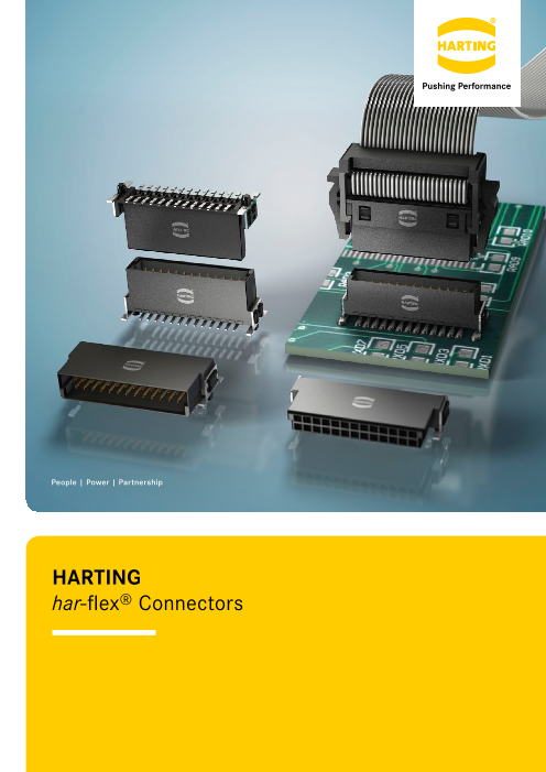
HARTING
har-flex® Connectors
Page2
H A R T I N G w o r l d w i d e
Transforming customer wishes
into concrete solutions
The HARTING Technology Group is skilled in the fields of electrical, electronic and optical
connection, transmission and networking, as well as in manufacturing, mechatronics and
software creation. The Group uses these skills to develop customized solutions and products
such as connectors for energy and data transmission applications including, for example,
mechanical engineering, rail technology, wind energy plants, factory automation and the
telecommunications sector. In addition, HARTING also produces electro-magnetic components for
the automobile industry and offers solutions in the field of Enclosures and Shop Systems.
The HARTING Group currently comprises 36 subsidiary companies and worldwide distributors
employing a total of more than 3,500 staff.
2
Page3
HARTING Subsidiary company HARTING Representatives
We aspire to top performance. Our people on location form the interface to the centrally
Connectors ensure functionality. As core elements coordinated development and production departments.
of electrical and optical wiring, connection and In this way, our customers can rely on consistently high,
infrastructure technologies, they are essential in superior product quality – worldwide.
enabling the modular construction of devices, machines
and systems across a very wide range of industrial Our claim: Pushing Performance.
applications. Their reliability is a crucial factor HARTING provides more than optimally attuned
guaranteeing smooth functioning in the manufacturing components. In order to serve our customers with the best
area, in telecommunications, applications in medical possible solutions, HARTING is able to contribute a great
technology – in fact, connectors are at work in virtually deal more and play a closely integrative role in the value
every conceivable application area. Thanks to the creation process.
consistent further development of our technologies, From ready assembled cables through to control racks
customers enjoy investment security and benefit from or ready-to-go control desks: Our aim is to generate
durable, long term functionality. the maximum benefits for our customers – without
compromise!
Always at hand, wherever our customers may be.
Increasing industrialization is creating growing Quality creates reliability – and warrants trust.
markets characterized by widely diverging demands and The HARTING brand stands for superior quality and
requirements. The search for perfection, increasingly reliability – worldwide. The standards we set are the
efficient processes and reliable technologies is a common result of consistent, stringent quality management that is
factor in all sectors across the globe. subject to regular certifications and audits.
HARTING is providing these technologies – in Europe, EN ISO 9001, the EU Eco-Audit and ISO 14001:2004 are
America and Asia. The HARTING professionals at our key elements here. We take a proactive stance to new
international subsidiaries engage in close, partnership requirements, which is why HARTING ranks among the
based interaction with our customers, right from the very first companies worldwide to have obtained the new IRIS
early product development phases, in order to realize quality certificate for rail vehicles.
customer demands and requirements in the best possible
manner.
3
Page4
H A R T I N G w o r l d w i d e
HARTING technology creates added value for customers. or ultrahigh frequency applications that are finding use
Technologies by HARTING are at work worldwide. in telecommunications or automation networks, in the
HARTING’s presence stands for smoothly functioning automotive industry, or in industrial sensor and actuator
systems, powered by intelligent connectors, smart applications, RFID and wireless technologies, in addition
infrastructure solutions and mature network systems. In to packaging and housing made of plastics, aluminum or
the course of many years of close, trust-based cooperation stainless steel.
with its customers, the HARTING Technology Group has
advanced to one of the worldwide leading specialists HARTING solutions extend across technology boundaries.
for connector technology. Extending beyond the basic Drawing on the comprehensive resources of the group’s
functionalities demanded, we offer individual customers technology pool, HARTING devises practical solutions
specific and innovative solutions. These tailored solutions for its customers. Whether this involves industrial
deliver sustained effects, provide investment security and networks for manufacturing automation, or hybrid
enable customers to achieve strong added value. interface solutions for wireless telecommunication
infrastructures, 3D circuit carriers with microstructures,
Opting for HARTING opens up an innovative, complex or cable assemblies for high-temperature applications
world of concepts and ideas. in the automotive industry – HARTING technologies
In order to develop connectivity and network solutions offer far more than components, and represent mature,
serving an exceptionally wide range of connector comprehensive solutions attuned to individual customer
applications and task scopes in a professional and cost requirements and wishes. The range covers ready-to-use
optimized manner, HARTING not only commands the full cable configurations, completely assembled backplanes
array of conventional tools and basic technologies. Over and board system carriers, as well as fully wired and
and beyond these capabilities, HARTING is constantly tested control panels.
harnessing and refining its broad base of knowledge In order to ensure the future proof design of RF- and
and experience to create new solutions that ensure EMC-compatible interface solutions, the central HARTING
continuity at the same time. In securing this know-how laboratory (certified to EN 45001) provides simulation
lead, HARTING draws on a wealth of sources from both in- tools, as well as experimental, testing and diagnostics
house research and the world of applications alike. facilities all the way through to scanning electron
Salient examples of these sources of innovative knowledge microscopes. In the selection of materials and processes,
include microstructure technologies, 3D design and lifecycle and environmental aspects play a key role, in
construction technology, as well as high temperature addition to product and process capability considerations.
4
Page5
HARTING knowledge is practical know-how generating The key focus is on applications in every solution
synergy effects. approach. In this context, uncompromising, superior
HARTING commands decades of experience with quality is our hallmark. Every new solution found will
regard to the applications conditions of connectors in invariably flow back into the HARTING technology pool,
telecommunications, computer and network technologies thereby enriching our resources. And every new solution
and medical technologies, as well as industrial automation we go on to create will draw on this wealth of resources in
technologies, such as the mechanical engineering order to optimize each and every individual solution. In
and plant engineering areas, in addition to the power this way, HARTING is synergy in action.
generation industry or the transportation sector. HARTING
is highly conversant with the specific application areas in
all of these technology fields.
gy Power
rgy
Wind Ener Generation and
olar
Ene Distr
S ibuti
tion
o
a packag
es Advanced T noo
ort icro
ls A
M
uto
sp
Ve m
3D ndin
s Simulation
g S
e y
Production Micro Structure
Technologies Technologies
PCB Interconnect Information
Technologies Technologies Technologies
Metal Treatment Network
Technologies Technologies
Mechatronic ab
d In
C
C do u
I
m stri ms
p a
k
u l C
r
t onnectors Actuator S
yste wo
i Netng S al ys ritem dus
t
s Broad edica
l In
cast and Entertainment M
5
Machinery Tran
Assembly lin
le Assemblies
nfrastructure
strial De
vices
Ind
u
ion
at
s
ste
m
es
ackp
lan
B
edd
e
b
E
m
Telecom
Page6
HARTING eCatalogue
The HARTING eCatalogue is an electronic catalogue
with a part configuration and 3D components library.
Here you can choose a connector according to your
requirements. Afterwards you are able to send your
inquiry directly to a HARTING sales partner.
The drawings to every single part are available in
PDF-format.
The parts are downloadable in 2D-format (DXF) and
3D-format (IGES, STEP).
Product selection
The 3D-models can be viewed with a VRML-viewer.
You can find the HARTING eCatalogue at
www.HARTING.com.
Product configuration
Product overview Product combination
Product samples: Fast-track delivery to your desk, free of charge
The new free express sample service in the HARTING eCatalogue allows customers to order samples
immediately, easily and completely free of charge. A broad selection from the device connectivity product
portfolio is now available. If a product is unavailable, the system offers alternative products with similar features
that can be requested at a mouse click.
The free samples are shipped within 24 hours at no cost to you. This service enables tremendous flexibility,
especially in the design phase of projects.
General information
It is the customer’s responsibility We reserve the right to modify No part of this catalogue may be reproduced in any
to check whether the components designs or substance of content form (print, photocopy, microfilm or any other process)
illustrated in this catalogue also in order to improve quality, or processed, duplicated or distributed by means of
comply with different regulations keep pace with technological electronic systems without the prior written consent of
from those stated in special fields of advancement or meet particular HARTING Electronics GmbH, Espelkamp. We are bound
applications. requirements in production. by the German version only.
6 © HARTING Electronics GmbH, Espelkamp – All rights reserved, including those of the translation.
Page7
Directory
connectors Page
connector system – introduction . . . . . . . . . . . . . . . . . . . . . . . . . . . . . . . 8
Technical characteristics . . . . . . . . . . . . . . . . . . . . . . . . . . . . . . . . . . . . . . . . . . 10
Male connectors, straight . . . . . . . . . . . . . . 14
Female connectors, straight . . . . . . . . . . . . 16
Male connectors, angled . . . . . . . . . . . . . . . 18
Female connectors, angled . . . . . . . . . . . . . 20
Cable assemblies . . . . . . . . . . . . . . . . . . . . 22
Company addresses . . . . . . . . . . . . . . . . . . . . . . . . . . . . . . . . . . . . . . . . . . . . . 25
7
Page8
Introduction
har-flex® coNNecToRs customer-specific solutions, thus HARTING can realize a short
With har-flex®, HARTING has developed a general-purpose PCB delivery time.
connector series for internal and external Device Connectivity. The
continuous scalability by an even number of contacts, i.e. from 6 to PRoducT dIveRsITy
100, of the HARTING‘s har-flex® mezzanine connector series is a The har-flex® product range with SMT termination technology is
special feature forming an ideal basis for customized applications. based on a 1.27 mm grid. With its diverse variants, HARTING provides
The advantage is clearly evident considering that the connector is connectivity solutions for many different board-to-board and cable-
always optimized to suit specific applications on the device PCB, to-board applications. For example, two straight connectors are used
while also covering the medium- and small-scale volume range that is for the mezzanine application, two angled connectors for PCBs on
typical for the production of industrial devices. one level, and a combination allows the well-known pairing of mother
and daughter cards. By using an IDC flat band cable, two PCBs with
This flexibility is new – HARTING turns an individual design into a large space between can be connected.
standard component. No special tooling changes are needed for
8
Page9
Introduction
Many pin count options
HARTING has developed a modular tooling concept which offers a
broad choice of configurations between 6 and 100 poles in even
numbered positions. This flexibility in the choice of number of
contacts, combined with high density contact spacing, allow the
designer to maximize the use of PCB real estate, thereby achieving
overall space savings and cost efficiencies.
Flexible board-to-board distances
HARTING covers mezzanine applications with a range of straight
versions for four different stacking heights that can be used
to interconnect PCBs arranged in parallel stacks with spacing
between 8.0 mm and 13.8 mm. Additional stacking heights are in
development. For applications requiring larger spacing between
boards HARTING offers compatible cable assemblies terminated
with insulation displacement technology.
Robust design
The special SMT fixing ensures a robust and enduring connection
to the PCB and helps to absorb mechanical stress on the solder
contacts resulting from insertion and removal forces.
Automated processing features
The har-flex® SMT connectors meet the highest demands in terms
of their processing capabilities. Special blister packaging provides
protection during shipping and handling, while the “pick and place“
pads enable automated assembly of the PCBs. The temperature
resistant materials of the insulating body, in combination with
consistent testing of the coplanarity of contacts, ensure reliable
soldering capabilities of the connectors in the reflow process.
9
Page10
Technical characteristics
Number of contacts 6, 8, 10 … 96, 98, 100 Current carrying capacity
acc. to IEC 60 512-5-2
The current carrying capacity is limited by maximum temperature
Connector pitch 1.27 mm x 1.27 mm of materials for inserts and contacts including terminals.The current capacity-curve is valid for continuous, not interrupted
[0.050’’ x 0.050’’] current-loaded contacts of connectors when simultaneous power
on all contacts is given, without exceeding the maximum tempe-
rature.
Clearance and creepage distance Control and test procedures according to DIN IEC 60 512-5-2.
Board connectors (SMT) min. 0.4 mm
Cable connectors (IDC)
AWG 30/1 (solid) min. 0.35 mm
AWG 30/7 (stranded) min. 0.4 mm
Test voltage Ur.m.s. 500 V
Contact resistance < 25 mΩ
Insulation resistance > 10 GΩ
Insertion and withdrawal force approx. 0.5 N / contact
Working temperature range
for connectors: – 55 °C … + 125 °C
for flat cable assembly: depends on cable type
The higher temperature limit
includes the local ambient and
heating effects of the contacts
under load Derating curve at Imax * 0.8 (IEC 60 512-5-2)
Temperature during reflow soldering min. 150 s > 217 °C
(acc. to ECA/IPC/JEDEC min. 30 s > 240 °C Durability
J-STD-075 Level PSL R0)
Performance level 1 (recommended for majority of applications)
Electrical termination Initial 250 mating cycles, 10 days gas test (25 °C/75 % r.h.) using H2S 10 ppb, NO2 200 ppb, CL2 10 ppb, SO2 200 ppb.
Board connectors SMT (Surface Mount Technology) Measurement of contact resistance. The remaining 250 mating
Cable connectors I DC (Insulation cycles are subject to measurement of contact resistance and
Displacement Connection) visual inspection. Visual inspection. No abrasion of the contact
finish through to the base material. No functional impairment.
Part number definition: 15 . . . . . 2 . . . . . .
Materials
Moulding material LCP Performance level 2
UL approval UL 94-V0 Initial 125 mating cycles, 4 days gas test (25 °C/75% r.h.) using H2S
CTI value 10 ppb, NO2 200 ppb, CL2 10 ppb, SO2 200 ppb. Measurement of
(Comparative Tracking Index) 175 contact resistance. The remaining 125 mating cycles are subject
to measurement of contact resistance and visual inspection.
Visual inspection. No abrasion of the contact finish through to
Contacts base material Copper alloy the base material. No functional impairment.
Part number definition: 15 . . . . . 6 . . . . . .
Contact surface
Mating side
Board connectors Au over PdNi Performance level S4
(acc. performance level)
Cable connectors Au over PdNi Defined contact surface of min. 0.06 µm Au over 0.7+0.2 µm PdNi.
(acc. performance level)
Termination side Part number definition: 15 . . . . . 5 . . . . . .
Board connectors (SMT) Sn
Cable connectors (IDC) Sn
10
Page11
Technical characteristics
Working voltage acc. to IEC 60 664-1 Explanations:
The working voltage depends on user specific operational ®
conditions. Depending on the installation category, the degree – CTI value and isolation group are fixed values by the har-flex
of pollution and the entire electrical environment, the working connector characteristics.
voltage is different. The standard IEC 60 664-1 specifies, in
general, the minimum insulation distances for equipment. But it – Installation category I: Equipment is intended for use only in
can also be used to determine the maximum working voltage with appliances or installation parts, in which no overvoltages
given requirements. can occur. Equipment in this installation category in normally
operated at extra low voltage.
The following table shows the most common conditions applicable
for the har-flex® connectors and exemplary calculations for the
working voltage. For installation category, degree of pollution and – I nstallation category II: Equipment is intended for use in
other requirements which are not shown in the table we refer to installations or parts of installations, in which lightning
the IEC 60 664-1. overvoltages need not be considered. Overvoltages caused by
switching must be taken into account.
Clearance / Creepage
distance 0.4 mm – Pollution degree 1: No pollution or only dry, non-conductive
CTI-Value < 400 pollution occurs. The pollution has no influence.
Isolation group III a/b
Case A Case B – Pollution degree 2: Only non-conductive pollution occurs. Electrical field type (Inhomogeneous field) (Homogeneous field) A temporary conductive caused by condensation must be expected occasionally.
Installation category I II I II
Degree of pollution 1 1 1 1
Working voltage max. 150 V 100 V 150 V 150 V
Part number definition
The har-flex® part numbers have 14 digits and are based on the following scheme:
1 5 X X X X X X X X X X X X
15 har-flex® family
Connector style
11 straight male connector
1.75 mm stacking height
12 straight male connector
3.25 mm stacking height
15 angled male connector
21 straight female connector
6.25 mm stacking height
22 straight female connector
9.05 mm stacking height
25 angled female connector
Number of contacts
Durability
2 performance
level 1
5 performance
level S4
6 performance
level 2
Termination
6 SMT termination
Counting number
Packaging
000 Tape and reel packaging
333 Samples 11
Page12
Technical characteristics
Stacking heights of straight connector versions Mating options
The har-flex® connectors cover mezzanine applications with a
range of straight versions for four different stacking heights that
can be used to interconnect PCBs arranged in parallel stacks Mezzanine connection
with spacing between 8.0 mm and 13.8 mm.
Male 1.75 mm Male 3.25 mm
Extender Card connection
Female 6.25 mm Female 9.05 mm
Due to the wiping lengths of 1.5 mm, these four connectors
cover the distance of 8 mm to 13.8 mm continuously.
14 mm
13 mm Mother-to-Daughtercard connection
12 mm
11 mm
10 mm
9 mm
8 mm
stacking male 1.75 mm male 3.25 mm male 1.75 mm male 3.25 mm
heights female 6.25 mm female 6.25 mm female 9.05 mm female 9.05 mm
PCB 8 mm - 9.5 mm - 10.8 mm - 12.3 mm -
distance 9.5 mm 11 mm 12.3 mm 13.8 mm
part 15 11 … 15 12 … 15 11 … 15 12 …
numbers 15 21 … 15 21 … 15 22 … 15 22 …
12
Page13
Technical characteristics
Mating conditions SMT processing notes
The har-flex® SMT con-
Inclination nectors meet the highest d emands in terms of their
processing capabilities.
The connectors are delivered
in a tape and reel packag-
ing optimized for a utomatic
assembly machines. A
vacuum cover enables the
automatic assembly with a
vacuum nozzle.
The insulation body material is high temperature resistant, and
due to the black colour a secure camera recognition is ensured.
For a reliable SMT solder process, the termination pins are
100 % checked for coplanarity.
Mismating
Process / Moisture Sensitivity
During the reflow solder process, the connector has to resist ex-
treme variations in temperature. Connectors consist in general
of both plastic and metal parts, which have a different behaviour
during the solder process. The Process Sensivity and also the
Moisture Sensivity are tested according the ECA/IPC/JEDEC
J-STD-075 specification.
Process Sensivity:
PSL means Process Sensitivity Level. PSL is a rating used to
identify a component that is solder process sensitive. Damages
of the connector after three times soldering are not permitted
(e.g. melted edges).
Tape acc. to IEC 60 286-3
Moisture Sensitivity:
MSL means Moisture Sensitivity Level. MSL is a rating indicat-
ing a component’s susceptibility to damage due to absorbed
moisture during storage. Damages of the connector after stor-
age in damp heat and three times soldering are not permitted
(e.g. blisters).
The har-flex® connectors are rated with PSL R0 and MSL 1.
This is the maximum possible rating in both categories. The
har-flex® connector resists three times soldering at the following
conditions without damages:
• min. 150 s beyond 217 °C (liquidus temperature, the melting
point of the solder paste)
• m in. 30 s beyond classification temperature (240 °C / 245 °C
for har-flex®)
• T emperature solder profile according to ECA/IPC/JEDEC
Tape dimensions: E J-STD-075
poles 6 to 12 24.4 • For MSL test, a storage of 168 hours at 85 °C and 85 % rel.
poles 14 to 20 32.4 humidity was carried out
poles 22 to 40 44.4
poles 42 to 56 56.4
poles 58 to 80 72.4 As the result, the har-flex
® connectors are not process sensi-
tive and not moisture sensitive according to ECA/IPC/JEDEC
poles 82 to 100 88.4 J-STD-075. 13
Page14
Male connectors, straight
Number
Identification of contacts Part No. Dimensions in mm
Male connector, straight, A B C D E F G
stacking heights 6 15 1 . 006 . 601 . . . 2.54 6.96 8.89 5.76 4.76 6.56 1.05
1.75 / 3.25 mm 8 15 1 . 008 . 601 . . . 3.81 8.23 10.16 7.03 6.03 7.83 1.69
10 15 1 . 010 . 601 . . . 5.08 9.50 11.43 8.30 7.30 9.10 2.32
12 15 1 . 012 . 601 . . . 6.35 10.77 12.70 9.57 8.57 10.37 2.96
14 15 1 . 014 . 601 . . . 7.62 12.04 13.97 10.84 9.84 11.64 3.59
16 15 1 . 016 . 601 . . . 8.89 13.31 15.24 12.11 11.11 12.91 4.23
18 15 1 . 018 . 601 . . . 10.16 14.58 16.51 13.38 12.38 14.18 4.48
20 15 1 . 020 . 601 . . . 11.43 15.85 17.78 14.65 13.65 15.45 5.50
22 15 1 . 022 . 601 . . . 12.70 17.12 19.05 15.92 14.92 16.72 6.13
24 15 1 . 024 . 601 . . . 13.97 18.39 20.32 17.19 16.19 17.99 6.77
26 15 1 . 026 . 601 . . . 15.24 19.66 21.59 18.46 17.46 19.26 7.40
28 15 1 . 028 . 601 . . . 16.51 20.93 22.86 19.73 18.73 20.53 8.04
30 15 1 . 030 . 601 . . . 17.78 22.20 24.13 21.00 20.00 21.80 8.67
32 15 1 . 032 . 601 . . . 19.05 23.47 25.40 22.27 21.27 23.07 9.31
34 15 1 . 034 . 601 . . . 20.32 24.74 26.67 23.54 22.54 24.34 9.94
36 15 1 . 036 . 601 . . . 21.59 26.01 27.94 24.81 23.81 25.61 10.58
38 15 1 . 038 . 601 . . . 22.86 27.28 29.21 26.08 25.08 26.88 11.21
40 15 1 . 040 . 601 . . . 24.13 28.55 30.48 27.35 26.35 28.15 11.85
42 15 1 . 042 . 601 . . . 25.40 29.82 31.75 28.62 27.62 29.42 12.48
44 15 1 . 044 . 601 . . . 26.67 31.09 33.02 29.89 28.89 30.69 13.12
46 15 1 . 046 . 601 . . . 27.94 32.36 34.29 31.16 30.16 31.96 13.75
48 15 1 . 048 . 601 . . . 29.21 33.63 35.56 32.43 31.43 33.23 14.39
50 15 1 . 050 . 601 . . . 30.48 34.90 36.83 33.70 32.70 34.50 15.02
52 15 1 . 052 . 601 . . . 31.75 36.17 38.10 34.97 33.97 35.77 15.66
54 15 1 . 054 . 601 . . . 33.02 37.44 39.37 36.24 35.24 37.04 16.29
56 15 1 . 056 . 601 . . . 34.29 38.71 40.64 37.51 36.51 38.31 16.93
58 15 1 . 058 . 601 . . . 35.56 39.98 41.91 38.78 37.78 39.58 17.56
60 15 1 . 060 . 601 . . . 36.83 41.25 43.18 40.05 39.05 40.85 18.20
62 15 1 . 062 . 601 . . . 38.10 42.52 44.45 41.32 40.32 42.12 18.83
64 15 1 . 064 . 601 . . . 39.37 43.79 45.72 42.59 41.59 43.39 19.47
66 15 1 . 066 . 601 . . . 40.64 45.06 46.99 43.86 42.86 44.66 20.10
68 15 1 . 068 . 601 . . . 41.91 46.33 48.26 45.13 44.13 45.93 20.74
70 15 1 . 070 . 601 . . . 43.18 47.60 49.53 46.40 45.40 47.20 21.37
72 15 1 . 072 . 601 . . . 44.45 48.87 50.80 47.67 46.67 48.47 22.01
74 15 1 . 074 . 601 . . . 45.72 50.14 52.07 48.94 47.94 49.74 22.64
76 15 1 . 076 . 601 . . . 46.99 51.41 53.34 50.21 49.21 51.01 23.28
78 15 1 . 078 . 601 . . . 48.26 52.68 54.61 51.48 50.48 52.28 23.91
80 15 1 . 080 . 601 . . . 49.53 53.95 55.88 52.75 51.75 53.55 24.55
82 15 1 . 082 . 601 . . . 50.80 55.22 57.15 54.02 53.02 54.82 25.18
84 15 1 . 084 . 601 . . . 52.07 56.49 58.42 55.29 54.29 56.09 25.82
86 15 1 . 086 . 601 . . . 53.34 57.76 59.69 56.56 55.56 57.36 26.45
88 15 1 . 088 . 601 . . . 54.61 59.03 60.96 57.83 56.83 58.63 27.09
90 15 1 . 090 . 601 . . . 55.88 60.30 62.23 59.10 58.10 59.90 27.72
92 15 1 . 092 . 601 . . . 57.15 61.57 63.50 60.37 59.37 61.17 28.36
94 15 1 . 094 . 601 . . . 58.42 62.84 64.77 61.64 60.64 62.44 28.99
Please insert digit 96 15 1 . 096 . 601 . . . 59.69 64.11 66.04 62.91 61.91 63.71 29.63
for stacking height 98 15 1 . 098 . 601 . . . 60.96 65.38 67.31 64.18 63.18 64.98 30.26
100 15 1 . 100 . 601 . . . 62.23 66.65 68.58 65.45 64.45 66.25 30.90
1.75 mm þ 1
14 3.25 mm þ 2
for performance level 1 2 333 for samples
for performance level S4 5 000 for 280 pieces on reel
for performance level 2 6
Page15
Male connectors, straight
Identification Drawing Dimensions in mm
Dimensions
stacking height with unmated
height vacuum cover height
Y X Z
1.75 7.6 6.6
3.25 9.1 8.1
PCB layout
15
Y
Z
X
Page16
Female connectors, straight
Number
Identification of contacts Part No. Dimensions in mm
Female connector, A B C D E G
straight, 6 15 2 . 006 . 601 . . . 2.54 6.96 8.89 5.56 4.56 1.19
stacking heights 8 15 2 . 008 . 601 . . . 3.81 8.23 10.16 6.83 5.83 1.19
6.25 / 9.05 mm 10 15 2 . 010 . 601 . . . 5.08 9.50 11.43 8.10 7.10 2.46
12 15 2 . 012 . 601 . . . 6.35 10.77 12.70 9.37 8.37 2.46
14 15 2 . 014 . 601 . . . 7.62 12.04 13.97 10.64 9.64 3.73
16 15 2 . 016 . 601 . . . 8.89 13.31 15.24 11.91 10.91 3.73
18 15 2 . 018 . 601 . . . 10.16 14.58 16.51 13.18 12.18 5.00
20 15 2 . 020 . 601 . . . 11.43 15.85 17.78 14.45 13.45 5.00
22 15 2 . 022 . 601 . . . 12.70 17.12 19.05 15.72 14.72 6.27
24 15 2 . 024 . 601 . . . 13.97 18.39 20.32 16.99 15.99 6.27
26 15 2 . 026 . 601 . . . 15.24 19.66 21.59 18.26 17.26 7.54
28 15 2 . 028 . 601 . . . 16.51 20.93 22.86 19.53 18.53 7.54
30 15 2 . 030 . 601 . . . 17.78 22.20 24.13 20.80 19.80 8.81
32 15 2 . 032 . 601 . . . 19.05 23.47 25.40 22.07 21.07 8.81
34 15 2 . 034 . 601 . . . 20.32 24.74 26.67 23.34 22.34 10.08
36 15 2 . 036 . 601 . . . 21.59 26.01 27.94 24.61 23.61 10.08
38 15 2 . 038 . 601 . . . 22.86 27.28 29.21 25.88 24.88 11.35
40 15 2 . 040 . 601 . . . 24.13 28.55 30.48 27.15 26.15 11.35
42 15 2 . 042 . 601 . . . 25.40 29.82 31.75 28.42 27.42 12.62
44 15 2 . 044 . 601 . . . 26.67 31.09 33.02 29.69 28.69 12.62
46 15 2 . 046 . 601 . . . 27.94 32.36 34.29 30.96 29.96 13.89
48 15 2 . 048 . 601 . . . 29.21 33.63 35.56 32.23 31.23 13.89
50 15 2 . 050 . 601 . . . 30.48 34.90 36.83 33.50 32.50 15.16
52 15 2 . 052 . 601 . . . 31.75 36.17 38.10 34.77 33.77 15.16
54 15 2 . 054 . 601 . . . 33.02 37.44 39.37 36.04 35.04 16.43
56 15 2 . 056 . 601 . . . 34.29 38.71 40.64 37.31 36.31 16.43
58 15 2 . 058 . 601 . . . 35.56 39.98 41.91 38.58 37.58 17.70
60 15 2 . 060 . 601 . . . 36.83 41.25 43.18 39.85 38.85 17.70
62 15 2 . 062 . 601 . . . 38.10 42.52 44.45 41.12 40.12 18.97
64 15 2 . 064 . 601 . . . 39.37 43.79 45.72 42.39 41.39 18.97
66 15 2 . 066 . 601 . . . 40.64 45.06 46.99 43.66 42.66 20.24
68 15 2 . 068 . 601 . . . 41.91 46.33 48.26 44.93 43.93 20.24
70 15 2 . 070 . 601 . . . 43.18 47.60 49.53 46.20 45.20 21.51
72 15 2 . 072 . 601 . . . 44.45 48.87 50.80 47.47 46.47 21.51
74 15 2 . 074 . 601 . . . 45.72 50.14 52.07 48.74 47.74 22.78
76 15 2 . 076 . 601 . . . 46.99 51.41 53.34 50.01 49.01 22.78
78 15 2 . 078 . 601 . . . 48.26 52.68 54.61 51.28 50.28 24.05
80 15 2 . 080 . 601 . . . 49.53 53.95 55.88 52.55 51.55 24.05
82 15 2 . 082 . 601 . . . 50.80 55.22 57.15 53.82 52.82 25.32
84 15 2 . 084 . 601 . . . 52.07 56.49 58.42 55.09 54.09 25.32
86 15 2 . 086 . 601 . . . 53.34 57.76 59.69 56.36 55.36 26.59
88 15 2 . 088 . 601 . . . 54.61 59.03 60.96 57.63 56.63 26.59
90 15 2 . 090 . 601 . . . 55.88 60.30 62.23 58.90 57.90 27.86
92 15 2 . 092 . 601 . . . 57.15 61.57 63.50 60.17 59.17 27.86
94 15 2 . 094 . 601 . . . 58.42 62.84 64.77 61.44 60.44 29.13
Please insert digit 96 15 2 . 096 . 601 . . . 59.69 64.11 66.04 62.71 61.71 29.13
for stacking height 98 15 2 . 098 . 601 . . . 60.96 65.38 67.31 63.98 62.98 30.40
100 15 2 . 100 . 601 . . . 62.23 66.65 68.58 65.25 64.25 30.40
6.25 mm þ 1
16 9.05 mm þ 2
for performance level 1 2 333 for samples
for performance level S4 5 000 for 280 pieces on reel
for performance level 2 6
Page17
Female connectors, straight
Identification Drawing Dimensions in mm
Dimensions
stacking height with
height vacuum cover
Y X
6.25 7.1
9.05 9.9
PCB layout
17
Y
X
Page18
Male connectors, angled
Number
Identification of contacts Part No. Dimensions in mm
Male connector, A B C D E
angled 6 15 15 006 . 601 . . . 2.54 6.96 8.89 5.76 4.76
8 15 15 008 . 601 . . . 3.81 8.23 10.16 7.03 6.03
10 15 15 010 . 601 . . . 5.08 9.50 11.43 8.30 7.30
12 15 15 012 . 601 . . . 6.35 10.77 12.70 9.57 8.57
14 15 15 014 . 601 . . . 7.62 12.04 13.97 10.84 9.84
16 15 15 016 . 601 . . . 8.89 13.31 15.24 12.11 11.11
18 15 15 018 . 601 . . . 10.16 14.58 16.51 13.38 12.38
20 15 15 020 . 601 . . . 11.43 15.85 17.78 14.65 13.65
22 15 15 022 . 601 . . . 12.70 17.12 19.05 15.92 14.92
24 15 15 024 . 601 . . . 13.97 18.39 20.32 17.19 16.19
26 15 15 026 . 601 . . . 15.24 19.66 21.59 18.46 17.46
28 15 15 028 . 601 . . . 16.51 20.93 22.86 19.73 18.73
30 15 15 030 . 601 . . . 17.78 22.20 24.13 21.00 20.00
32 15 15 032 . 601 . . . 19.05 23.47 25.40 22.27 21.27
34 15 15 034 . 601 . . . 20.32 24.74 26.67 23.54 22.54
36 15 15 036 . 601 . . . 21.59 26.01 27.94 24.81 23.81
38 15 15 038 . 601 . . . 22.86 27.28 29.21 26.08 25.08
40 15 15 040 . 601 . . . 24.13 28.55 30.48 27.35 26.35
42 15 15 042 . 601 . . . 25.40 29.82 31.75 28.62 27.62
44 15 15 044 . 601 . . . 26.67 31.09 33.02 29.89 28.89
46 15 15 046 . 601 . . . 27.94 32.36 34.29 31.16 30.16
48 15 15 048 . 601 . . . 29.21 33.63 35.56 32.43 31.43
50 15 15 050 . 601 . . . 30.48 34.90 36.83 33.70 32.70
52 15 15 052 . 601 . . . 31.75 36.17 38.10 34.97 33.97
54 15 15 054 . 601 . . . 33.02 37.44 39.37 36.24 35.24
56 15 15 056 . 601 . . . 34.29 38.71 40.64 37.51 36.51
58 15 15 058 . 601 . . . 35.56 39.98 41.91 38.78 37.78
60 15 15 060 . 601 . . . 36.83 41.25 43.18 40.05 39.05
62 15 15 062 . 601 . . . 38.10 42.52 44.45 41.32 40.32
64 15 15 064 . 601 . . . 39.37 43.79 45.72 42.59 41.59
66 15 15 066 . 601 . . . 40.64 45.06 46.99 43.86 42.86
68 15 15 068 . 601 . . . 41.91 46.33 48.26 45.13 44.13
70 15 15 070 . 601 . . . 43.18 47.60 49.53 46.40 45.40
72 15 15 072 . 601 . . . 44.45 48.87 50.80 47.67 46.67
74 15 15 074 . 601 . . . 45.72 50.14 52.07 48.94 47.94
76 15 15 076 . 601 . . . 46.99 51.41 53.34 50.21 49.21
78 15 15 078 . 601 . . . 48.26 52.68 54.61 51.48 50.48
80 15 15 080 . 601 . . . 49.53 53.95 55.88 52.75 51.75
82 15 15 082 . 601 . . . 50.80 55.22 57.15 54.02 53.02
84 15 15 084 . 601 . . . 52.07 56.49 58.42 55.29 54.29
86 15 15 086 . 601 . . . 53.34 57.76 59.69 56.56 55.56
88 15 15 088 . 601 . . . 54.61 59.03 60.96 57.83 56.83
90 15 15 090 . 601 . . . 55.88 60.30 62.23 59.10 58.10
92 15 15 092 . 601 . . . 57.15 61.57 63.50 60.37 59.37
94 15 15 094 . 601 . . . 58.42 62.84 64.77 61.64 60.64
96 15 15 096 . 601 . . . 59.69 64.11 66.04 62.91 61.91
98 15 15 098 . 601 . . . 60.96 65.38 67.31 64.18 63.18
100 15 15 100 . 601 . . . 62.23 66.65 68.58 65.45 64.45
18
for performance level 1 2 333 for samples
for performance level S4 5 000 for 560 pieces on reel
for performance level 2 6
Page19
Male connectors, angled
Identification Drawing Dimensions in mm
Dimensions
PCB layout
19
Page20
Female connectors, angled
Number
Identification of contacts Part No. Dimensions in mm
Female connector, A B C D E
angled 6 15 25 006 . 601 . . . 2.54 6.96 8.89 5.56 4.56
8 15 25 008 . 601 . . . 3.81 8.23 10.16 6.83 5.83
10 15 25 010 . 601 . . . 5.08 9.50 11.43 8.10 7.10
12 15 25 012 . 601 . . . 6.35 10.77 12.70 9.37 8.37
14 15 25 014 . 601 . . . 7.62 12.04 13.97 10.64 9.64
16 15 25 016 . 601 . . . 8.89 13.31 15.24 11.91 10.91
18 15 25 018 . 601 . . . 10.16 14.58 16.51 13.18 12.18
20 15 25 020 . 601 . . . 11.43 15.85 17.78 14.45 13.45
22 15 25 022 . 601 . . . 12.70 17.12 19.05 15.72 14.72
24 15 25 024 . 601 . . . 13.97 18.39 20.32 16.99 15.99
26 15 25 026 . 601 . . . 15.24 19.66 21.59 18.26 17.26
28 15 25 028 . 601 . . . 16.51 20.93 22.86 19.53 18.53
30 15 25 030 . 601 . . . 17.78 22.20 24.13 20.80 19.80
32 15 25 032 . 601 . . . 19.05 23.47 25.40 22.07 21.07
34 15 25 034 . 601 . . . 20.32 24.74 26.67 23.34 22.34
36 15 25 036 . 601 . . . 21.59 26.01 27.94 24.61 23.61
38 15 25 038 . 601 . . . 22.86 27.28 29.21 25.88 24.88
40 15 25 040 . 601 . . . 24.13 28.55 30.48 27.15 26.15
42 15 25 042 . 601 . . . 25.40 29.82 31.75 28.42 27.42
44 15 25 044 . 601 . . . 26.67 31.09 33.02 29.69 28.69
46 15 25 046 . 601 . . . 27.94 32.36 34.29 30.96 29.96
48 15 25 048 . 601 . . . 29.21 33.63 35.56 32.23 31.23
50 15 25 050 . 601 . . . 30.48 34.90 36.83 33.50 32.50
52 15 25 052 . 601 . . . 31.75 36.17 38.10 34.77 33.77
54 15 25 054 . 601 . . . 33.02 37.44 39.37 36.04 35.04
56 15 25 056 . 601 . . . 34.29 38.71 40.64 37.31 36.31
58 15 25 058 . 601 . . . 35.56 39.98 41.91 38.58 37.58
60 15 25 060 . 601 . . . 36.83 41.25 43.18 39.85 38.85
62 15 25 062 . 601 . . . 38.10 42.52 44.45 41.12 40.12
64 15 25 064 . 601 . . . 39.37 43.79 45.72 42.39 41.39
66 15 25 066 . 601 . . . 40.64 45.06 46.99 43.66 42.66
68 15 25 068 . 601 . . . 41.91 46.33 48.26 44.93 43.93
70 15 25 070 . 601 . . . 43.18 47.60 49.53 46.20 45.20
72 15 25 072 . 601 . . . 44.45 48.87 50.80 47.47 46.47
74 15 25 074 . 601 . . . 45.72 50.14 52.07 48.74 47.74
76 15 25 076 . 601 . . . 46.99 51.41 53.34 50.01 49.01
78 15 25 078 . 601 . . . 48.26 52.68 54.61 51.28 50.28
80 15 25 080 . 601 . . . 49.53 53.95 55.88 52.55 51.55
82 15 25 082 . 601 . . . 50.80 55.22 57.15 53.82 52.82
84 15 25 084 . 601 . . . 52.07 56.49 58.42 55.09 54.09
86 15 25 086 . 601 . . . 53.34 57.76 59.69 56.36 55.36
88 15 25 088 . 601 . . . 54.61 59.03 60.96 57.63 56.63
90 15 25 090 . 601 . . . 55.88 60.30 62.23 58.90 57.90
92 15 25 092 . 601 . . . 57.15 61.57 63.50 60.17 59.17
94 15 25 094 . 601 . . . 58.42 62.84 64.77 61.44 60.44
96 15 25 096 . 601 . . . 59.69 64.11 66.04 62.71 61.71
98 15 25 098 . 601 . . . 60.96 65.38 67.31 63.98 62.98
100 15 25 100 . 601 . . . 62.23 66.65 68.58 65.25 64.25
20
for performance level 1 2 333 for samples
for performance level S4 5 000 for 560 pieces on reel
for performance level 2 6