


DISCREPANCY SWITCH BHL TYPE
Product Catalog
Document Information
| Document Title | DISCREPANCY SWITCH BHL TYPE |
|---|---|
| Document Type | Product Catalog |
| File size | 2Mb |
| Category | |
| Company | FUJI ELECTRIC INDUSTRY CO., LTD. (Documents List) |
Documents related to this company


Document Contents
Page1
● ● ● DISCREPANCY SWITCH
BHL type
Page2
DISCREPANCY SWITCH
BHL TYPE
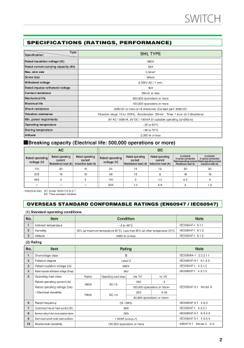
SPECIFICATIONS (RATINGS, PERFORMANCE)
Type
Specification BHL TYPE
Rated insulation voltage (Ui) 690V
Rated current-carrying capacity (Ith) 20A
Max. wire size 5.5mm2
Screw size M4×9
Withstand voltage 2,500V AC / 1 min.
Rated impulse withstand voltage 4kV
Contact resistance 50mΩ or less
Mechanical life 500,000 operations or more
Electrical life 100,000 operations or more
Shock resistance 500m/s2 or more (in 6 directions) (Contact part: 300m/s2)
Vibration resistance Vibration range: 10 to 150Hz, Acceleration: 20m/s2, Time: 1 hour (in 3 directions)
Min. power requirments 5V AC / 500mA, 5V DC / 100mA (in suitable operating conditions)
Operating temperature –20 to 60°C
Storing temperature –40 to 70°C
Altitude 2,000 m or less
■Breaking capacity (Electrical life: 500,000 operations or more)
AC DC
Rated operating Rated operating Rated operating Rated operating Rated operating Rated operating 2 contacts 2 contacts
voltage (V) current current current in series connection in series connection
Rated operating current Rated operating current
Resistance load (A) Inductive load (A) voltage (V) current
Resistance load (A) Inductive load (A) Resistance load (A) Inductive load (A)
110 20 15 24 15 10 20 20
FEATURES 220 15 10 48 10 6 18 15
440 4 3 110 3 1.5 4.5 4
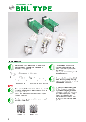
With the rolling action of the contact, it’s minimize the There are types of key that are - - - 220 1.2 0.8 2 1.5
area exposed to arc, there by high stability can be Cylinder type (BHLC type) and ∗Inductive load AC: power factor 0.6 to 0.7
maintained for a long period. padlock type (BHLP type) keys can DC: Time constant 40±6ms
be prepared.
The key lock mechanism can prevents OVERSEAS STANDARD CONFORMABLE RATINGS (EN60947 / IEC60947)
Breaking starts Rolling action erroneous operation.
(1) Standard operating conditions
No. Item Condition Note
In case of back terminal type (BHL-B
type), terminal screws to wiring are 1 Ambient temperature –5 to 40°C IEC60947-1 6.1.1
aggregated on the back of the switch, 2 Humidity 50% (at maximum temperature 40°C), Less than 90% (at other temperature 20°C) IEC60947-1 6.1.3
Contact starts Rolling action Contact completes it's possible to quick wiring. 3 Altitude 2000 m or less IEC60947-1 6.1.2
(2) Rating
NEW!
A BHLFX type that conforms to the No. Item Rating Note
An L3 type adopted the front access method. So, LED unit IP40 enclosure rating is available.
can be changed easily, if you need to maintain or change 1 Overvoltage class Ⅲ IEC60664-1 2.2.2.1.1
Since the knob position is fastened
power supply voltage. with a screw, the BHLFX type can be 2 Pollution degree Level 3 IEC60947-5-1 6.1.3.2
(Please refer to the page 8 for method of removing and prevent from getting into a foreign 3 Rated insulation voltage (Ui) 690V IEC60947-1 4.3.1.2
mounting for L3 type.) object from the outside, also 4 Rated impulse withstand voltage (Uimp) 4kV IEC60947-1 4.3.1.3
unexpected contact with live parts. 5 Operating load class Name Operating load class Ue(V) Ie(A)
Round and square types of nameplates can be selected A protective ground terminal is also Rated operating current (Ie) 240 3
according to your needs. provided. A600 AC-15
Rated operating voltage (Ue) 100,000 operations or more∗ IEC60947-5-1 Annex A
∗ Electrical durability 250 0.55
P600 DC-13
20,000 operations or more∗
6 Rated frequency 50 / 60Hz IEC60947-5-1 4.3.3
7 Customary free air heat current (Ith) 20A IEC60947-1 4.3.2.1
8 Maximum rating of short-circuit protection device 20A IEC60947-5-1 8.3.4.3
9 Short-circuit current under rated conditions 1,000A (cosφ=1) IEC60947-5-1 4.3.6.4
10
Square (Y) type Round (Z) type Mechanical durability 100,000 operations or more 60947-5-1 Annex C C.2
1
Page3
DISCREPANCY SWITCH
BHL TYPE SWITCH
SPECIFICATIONS (RATINGS, PERFORMANCE)
Type
Specification BHL TYPE
Rated insulation voltage (Ui) 690V
Rated current-carrying capacity (Ith) 20A
Max. wire size 5.5mm2
Screw size M4×9
Withstand voltage 2,500V AC / 1 min.
Rated impulse withstand voltage 4kV
Contact resistance 50mΩ or less
Mechanical life 500,000 operations or more
Electrical life 100,000 operations or more
Shock resistance 500m/s2 or more (in 6 directions) (Contact part: 300m/s2)
Vibration resistance Vibration range: 10 to 150Hz, Acceleration: 20m/s2, Time: 1 hour (in 3 directions)
Min. power requirments 5V AC / 500mA, 5V DC / 100mA (in suitable operating conditions)
Operating temperature –20 to 60°C
Storing temperature –40 to 70°C
Altitude 2,000 m or less
■Breaking capacity (Electrical life: 500,000 operations or more)
AC DC
Rated operating Rated operating Rated operating Rated operating Rated operating Rated operating 2 contacts 2 contacts
voltage (V) current current current in series connection in series connection
Rated operating current Rated operating current
Resistance load (A) Inductive load (A) voltage (V) current
Resistance load (A) Inductive load (A) Resistance load (A) Inductive load (A)
110 20 15 24 15 10 20 20
FEATURES 220 15 10 48 10 6 18 15
440 4 3 110 3 1.5 4.5 4
With the rolling action of the contact, it’s minimize the There are types of key that are - - - 220 1.2 0.8 2 1.5
area exposed to arc, there by high stability can be Cylinder type (BHLC type) and ∗Inductive load AC: power factor 0.6 to 0.7
maintained for a long period. padlock type (BHLP type) keys can DC: Time constant 40±6ms
be prepared.
The key lock mechanism can prevents OVERSEAS STANDARD CONFORMABLE RATINGS (EN60947 / IEC60947)
Breaking starts Rolling action erroneous operation.
(1) Standard operating conditions
No. Item Condition Note
In case of back terminal type (BHL-B
type), terminal screws to wiring are 1 Ambient temperature –5 to 40°C IEC60947-1 6.1.1
aggregated on the back of the switch, 2 Humidity 50% (at maximum temperature 40°C), Less than 90% (at other temperature 20°C) IEC60947-1 6.1.3
Contact starts Rolling action Contact completes it's possible to quick wiring. 3 Altitude 2000 m or less IEC60947-1 6.1.2
(2) Rating
NEW!
A BHLFX type that conforms to the No. Item Rating Note
An L3 type adopted the front access method. So, LED unit IP40 enclosure rating is available.
can be changed easily, if you need to maintain or change 1 Overvoltage class Ⅲ IEC60664-1 2.2.2.1.1
Since the knob position is fastened
power supply voltage. with a screw, the BHLFX type can be 2 Pollution degree Level 3 IEC60947-5-1 6.1.3.2
(Please refer to the page 8 for method of removing and prevent from getting into a foreign 3 Rated insulation voltage (Ui) 690V IEC60947-1 4.3.1.2
mounting for L3 type.) object from the outside, also 4 Rated impulse withstand voltage (Uimp) 4kV IEC60947-1 4.3.1.3
unexpected contact with live parts. 5 Operating load class Name Operating load class Ue(V) Ie(A)
Round and square types of nameplates can be selected A protective ground terminal is also Rated operating current (Ie) 240 3
according to your needs. provided. A600 AC-15
Rated operating voltage (Ue) 100,000 operations or more∗ IEC60947-5-1 Annex A
∗ Electrical durability 250 0.55
P600 DC-13
20,000 operations or more∗
6 Rated frequency 50 / 60Hz IEC60947-5-1 4.3.3
7 Customary free air heat current (Ith) 20A IEC60947-1 4.3.2.1
8 Maximum rating of short-circuit protection device 20A IEC60947-5-1 8.3.4.3
9 Short-circuit current under rated conditions 1,000A (cosφ=1) IEC60947-5-1 4.3.6.4
10
Square (Y) type Round (Z) type Mechanical durability 100,000 operations or more 60947-5-1 Annex C C.2
1 2
Page4
DISCREPANCY SWITCH
BHL TYPE
HOW TO ORDER STANDARD SPECIFICATION PRODUCTS
Standard type (2-position changeover)
BHL-1□ Operation method: Manual switching type Drawing is L3 type
① ② ③ ④ ⑤ ⑥ ⑦ ⑧ ⑨ ⑩
4-φ5 holes 36 Lamp power source Panel(t=1 to 3.2) Flange shape:Y(Square)
No. 項 目 Code Detail Remarks Terminal screw M4×9 (costumer) (27)
4 □55
5.5mm²(max.) (2)
BHL Standard type ― 5(Push stroke)
BHLS Small knob type ― 40
φ Point
HLC Cylinder key type ― (Black) Mask
① Basic type B (Silver)
Knob W(Milky white)
BHLP Padlock type ― Mounting hole Flange
(5) Flange shape:Z(Round)
BHL-B Back terminal type *Only “L2 type” L φ60.6
BHLFX Fixed knob + housing protection ground terminal ― No. of units 1 2 3 4 5 6
1 2-position chageover ― L(mm) 137 150 163 176 189 202
Push after 2-position chageover
② Operation method 2 *Only “BHL” and “BHLFX”
A B C D E
3 Push and turn to right / left after 2-position chageover ―
Standard type (Push after 2-position changeover)
4 Pushing and turning to right or left *Except “BHLS” and “BHL-B” BHL-2□ Operation method: Manual switching type (Push operation is enabled at each position.) Drawing is L3 type
A *Only “Operation 1”
Lamp power source 8(Push stroke)
4-φ5 holes 36
2-Point (costumer) Panel(t=1 to 3.2)
B ― Terminal screw M4×9 (27) Flange shape:Y(Square)
switching Pushing 4
5.5mm²(max.) (2) □55
C ― 40
φ
③ Operating position
D ― Knob W
Mounting hole (Milky white)
5 Ma
E ― (5) Flange Point sk
L (Black) (Silver)
Flange shape:Z(Round)
φ60.6
S *Only “Operation 4” No. of units 1 2 3 4 5 6
④ Number of units 1 to 6 Up to 6 units (12 contacts) L(mm) 197 210 223 236 249 262
B C D E
⑤ t Check the model identification table (on 9 to 10).
Circuit number 3-digi
indication ※ For specifications of other types, please make inquiry to Fuji Electric Industry. Standard type (Push and turn right / left after 2-position changeover)
L2 type L3 type BHL-3□ Operation method: Manual switching type (90°) / Push & automatic return type (30°) Drawing is L3 type
000 ― No LED Lamp power source =1 to 3.2)
4-φ5 holes 36 Panel(t Flange shape:Y
Terminal screw M4×9 (costumer) (27) (Square)
4 □55
024 ― 24V AC/DC 5.5mm²(max.) (2)
5(Push stroke)
030 ― 30V AC/DC
40
φ
⑥ Lamp voltage 048 Point
― 48V AC/DC (Black) Mask
(Silver)
110 110V DC 110V AC/DC Knob W(Milky white)
125 Mounting hole Flange
(5) Flange shape:Z(Round)
125V DC 125V AC/DC L φ60.6
220 220V DC 220V AC/DC
240 ― 230/ 240V AC/DC No. of units 1 2 3 4 5 6
BHLS BHL and others L(mm) 137 150 163 176 189 202
Indication method B C D E
⑦ (with built-in resistor) L2 Connector type LED lamp(built in resistance) Display color:Red / Green ― ○
L3 LED indicator Display color:Milky white ○ ○ ディスクレパンシースイッチ
BHL-4□ Operation method: Push & automatic return type (30°) Drawing is L3 type
W Milky white (Silver mask black point) / Standard color for indication of “L3” type ○ ○
Lamp power source Panel(t=1 to 3.2)
C Clear / Standard color for indication of “L2” type 4-φ5 holes 36 Flange shape:Y(Square)
Terminal screw M4×9 (costumer) (27)
⑧ Knob color ― ○ 4 □55
5.5mm²(max.) (2)
WB 5(Push stroke)
Milky white (Black mask black point) / Special color ○ ○
WFX BHLFX only ― ○ 40
φ Point
Y-B Square Black (N1.5) (Black) Mask
(Silver)
Knob W(Milky white)
Flange shape Y-BG Square Blue green (7.5BG4/1.5)
⑨ Flange
and color Mounting hole (5) Flange shape:Z(Round)
Z-B Round Black (N1.5) L φ60.6
Z-BG Round Blue green (7.5BG4/1.5)
⑩ Nameplate Please select name No. from page 7. No. of units 1 2 3 4 5 6
Munsell approximate value is indicated in ( ). L(mm) 137 150 163 176 189 202
S
3
36
36 36 36
12 12
12 (37) (37)
(37)
12
(37)
Page5
DISCREPANCY SWITCH
BHL TYPE SWITCH
HOW TO ORDER STANDARD SPECIFICATION PRODUCTS
Standard type (2-position changeover)
BHL-1□ Operation method: Manual switching type Drawing is L3 type
① ② ③ ④ ⑤ ⑥ ⑦ ⑧ ⑨ ⑩
4-φ5 holes 36 Lamp power source Panel(t=1 to 3.2) Flange shape:Y(Square)
No. 項 目 Code Detail Remarks Terminal screw M4×9 (costumer) (27)
4 □55
5.5mm²(max.) (2)
BHL Standard type ― 5(Push stroke)
BHLS Small knob type ― 40
φ Point
HLC Cylinder key type ― (Black) Mask
① Basic type B (Silver)
Knob W(Milky white)
BHLP Padlock type ― Mounting hole Flange
(5) Flange shape:Z(Round)
BHL-B Back terminal type *Only “L2 type” L φ60.6
BHLFX Fixed knob + housing protection ground terminal ― No. of units 1 2 3 4 5 6
1 2-position chageover ― L(mm) 137 150 163 176 189 202
Push after 2-position chageover
② Operation method 2 *Only “BHL” and “BHLFX”
A B C D E
3 Push and turn to right / left after 2-position chageover ―
Standard type (Push after 2-position changeover)
4 Pushing and turning to right or left *Except “BHLS” and “BHL-B” BHL-2□ Operation method: Manual switching type (Push operation is enabled at each position.) Drawing is L3 type
A *Only “Operation 1”
Lamp power source 8(Push stroke)
4-φ5 holes 36
2-Point (costumer) Panel(t=1 to 3.2)
B ― Terminal screw M4×9 (27) Flange shape:Y(Square)
switching Pushing 4
5.5mm²(max.) (2) □55
C ― 40
φ
③ Operating position
D ― Knob W
Mounting hole (Milky white)
5 Ma
E ― (5) Flange Point sk
L (Black) (Silver)
Flange shape:Z(Round)
φ60.6
S *Only “Operation 4” No. of units 1 2 3 4 5 6
④ Number of units 1 to 6 Up to 6 units (12 contacts) L(mm) 197 210 223 236 249 262
B C D E
⑤ t Check the model identification table (on 9 to 10).
Circuit number 3-digi
indication ※ For specifications of other types, please make inquiry to Fuji Electric Industry. Standard type (Push and turn right / left after 2-position changeover)
L2 type L3 type BHL-3□ Operation method: Manual switching type (90°) / Push & automatic return type (30°) Drawing is L3 type
000 ― No LED Lamp power source =1 to 3.2)
4-φ5 holes 36 Panel(t Flange shape:Y
Terminal screw M4×9 (costumer) (27) (Square)
4 □55
024 ― 24V AC/DC 5.5mm²(max.) (2)
5(Push stroke)
030 ― 30V AC/DC
40
φ
⑥ Lamp voltage 048 Point
― 48V AC/DC (Black) Mask
(Silver)
110 110V DC 110V AC/DC Knob W(Milky white)
125 Mounting hole Flange
(5) Flange shape:Z(Round)
125V DC 125V AC/DC L φ60.6
220 220V DC 220V AC/DC
240 ― 230/ 240V AC/DC No. of units 1 2 3 4 5 6
BHLS BHL and others L(mm) 137 150 163 176 189 202
Indication method B C D E
⑦ (with built-in resistor) L2 Connector type LED lamp(built in resistance) Display color:Red / Green ― ○
L3 Standard type (Pushing and turning to right or left)
LED indicator Display color:Milky white ○ ○
BHL-4□ Operation method: Push & automatic return type (30°) Drawing is L3 type
W Milky white (Silver mask black point) / Standard color for indication of “L3” type ○ ○
Lamp power source Panel(t=1 to 3.2)
C Clear / Standard color for indication of “L2” type 4-φ5 holes 36
Terminal screw M4×9 (costumer) (27) Flange shape:Y(Square)
⑧ Knob color ― ○ 4 □55
5.5mm²(max.) (2)
WB 5(Push stroke)
Milky white (Black mask black point) / Special color ○ ○
WFX BHLFX only ― ○ 40
φ Point
Y-B Square Black (N1.5) (Black) Mask
(Silver)
Knob W(Milky white)
Flange shape Y-BG Square Blue green (7.5BG4/1.5)
⑨ Flange
and color Mounting hole (5) Flange shape:Z(Round)
Z-B Round Black (N1.5) L φ60.6
Z-BG Round Blue green (7.5BG4/1.5)
⑩ Nameplate Please select name No. from page 7. No. of units 1 2 3 4 5 6
Munsell approximate value is indicated in ( ). L(mm) 137 150 163 176 189 202
S
3 4
36
36 36 36
12 12
12 (37) (37)
(37)
12
(37)
Page6
DISCREPANCY SWITCH
BHL TYPE
STANDARD SPECIFICATION PRODUCTS
Small-size type (2-position changeover) With key lock mechanism type Please refer to the page 8 for KEY SYSTEM.
BHLS-1□ Operation method: Manual switching type Drawing is L3 type BHLC Drawing is L3 type
36 4-φ5 holes
Lamp power source(costumer) Flange shape:Y(Square)
Lamp power source(costumer) (27)
4-φ5 holes 28 Terminal screw L (5)
Panel(t=2.3 to 3.2) 4 5(Push stroke) □55
M4×9 (5) 13 21 98 Flange shape:Y(Square) (2)
4
(2) □44 40
5(Stroke) φ
30
φ Knob W(Milky white)
Panel(t=1 to 3.2) Flange
Mask Jumper Point Mask
(Silver) (Black) (Silver)
φ22
L
Knob φ
Mounting hole Point 1 6.3
9.5 Terminal screw M4×9 Flange shape:Z(Round)
Flange (Black) 16 5.5mm²(max.) φ60.6
Flange shape:Z(Round)
φ50 Mounting hole
No. of units 1 2 3 4 5 6
L(mm) 158 171 184 197 210 223
No. of units * The key is TAKIGEN C-88 and C-110.
1 2 3 4 5 6 With padlock mechanism type φ22
L(mm) 155 168 181 194 207 220
A B C D E BHLP Drawing is L3 type
Lamp power source
36 4-φ5 holes (costumer) Panel(t=1 to 3.2) (27) Flange shape:Y(Square)
4 5(Push stroke) □55
(2)
φ4
0
Small-size type (Push after 2-position changeover)
BHLS-2□ Operation method: Manual switching type (Push operation is enabled at each position.) Drawing is L3 type Knob W(Milky white)
Flange Point
φ20.5 (Black) Mask
Pushing (Silver)
Lamp power source(costumer) Panel(t=2.3 to 3.2) (5) Padlock Padlockφ6
28 L L 80
(2) 8(Stroke)
4-φ5 holes (5) 2-Point
switching Pushing 13 21 98 Flange shape:Y(Square) Terminal screw M4×9
5.5mm²(max.)
4 Flange shape:Z(Round)
□44 Mounting hole φ60.6
30
φ No. of units 1 2 3 4 5 6
L(mm) 158 171 184 197 210 223
Mounting hole Knob Point Mask
Flange (Black) (Silver) ∗ Padlock is not included in the product. (Use a padlock with a 6 mm diameter.)
Resistor unit
Terminal screw M4×9 Flange shape:Z(Round) With Rear terminal type
φ50 BHL-B 36 4 Flange shape:Y(Square)
4-φ5 holes 61 187.5(including back terminals) 55
12
No. of units 5(Push stroke)
2-poistion switching contact 1 2 3 4 40
φ
Push-operation contact 1 2 1 2 1 1
B C D E L(mm) 215 241 228 254 241 254
Panel(t=2 to 4) 28
Mounting hole Flange shape:Z(Round)
φ60.6
12
Small-size type (Push and turn right / left after 2-position changeover) ∗ The BHL-B type can accept up to 3 units (6 contacts).
BHLS-3□ Operation method: Manual switching type (90°) / Push & automatic return type (30°) Drawing is L3 type
Lamp power source(costumer)
28 Terminal screw L
4- Panel(t=2.3 to 3.2)
φ5 holes M4×9 (5) 13 21 98 Flange shape:Y(Square)
4
(2) □44
5(Stroke) With fixed knob + housing protection ground terminal type (IP40)
BHLFX Terminal screw Drawing is L3 type
30
φ M4×9 Lamp power source Panel(t=1 to 3.2)
5.5mm²(max.) (costumer) Flange shape:Y(Square)
Mask 36 (27)
4 □55
4-φ5 holes (2)
(Silver) 5(Push stroke)
Knob
Mounting hole Point
Flange (Black)
Flange shape:Z(Round) 40
φ Point Mask
φ50 (Black) (Silver)
Knob WXF
(Milky white)
(5) A handle can be removed
L Flange if this screw is removed.
Mounting hole Flange shape:Z(Round)
No. of units 1 2 3 4 5 6 φ60.6
L(mm) 155 168 181 194 207 220
B C D E No. of units 1 2 3 4 5 6
L(mm) 137 150 163 176 189 202
5
28 28
28
φ28 φ28
44 44
φ28
44
36
36
50±0.2
36 36 50±0.2
68
φ22
12
12 (37)
12 (37)
(37) φ37
50
50
φ25 φ25
55
ランプ端子 ランプ端子
Terminal for lamp 2-1 3-4 Terminal for lamp
L1 L2 L1 L2
L1 L2 L1 L2
2-1 3-4 2-1 3-4
ランプ端子
6-5 7-8 Terminal for lampL1 L2 6-5 7-8
L1 L2
6-5 7-8
Page7
DISCREPANCY SWITCH
BHL TYPE SWITCH
STANDARD SPECIFICATION PRODUCTS
Small-size type (2-position changeover) With key lock mechanism type Please refer to the page 8 for KEY SYSTEM.
BHLS-1□ Operation method: Manual switching type Drawing is L3 type BHLC Drawing is L3 type
36 4-φ5 holes
Lamp power source(costumer) Flange shape:Y(Square)
Lamp power source(costumer) (27)
4-φ5 holes 28 Terminal screw L (5)
Panel(t=2.3 to 3.2) 4 5(Push stroke) □55
M4×9 (5) 13 21 98 Flange shape:Y(Square) (2)
4
(2) □44 40
5(Stroke) φ
30
φ Knob W(Milky white)
Panel(t=1 to 3.2) Flange
Mask Jumper Point Mask
(Silver) (Black) (Silver)
φ22
L
Knob φ
Mounting hole Point 1 6.3
9.5 Terminal screw M4×9 Flange shape:Z(Round)
Flange (Black) 16 5.5mm²(max.) φ60.6
Flange shape:Z(Round)
φ50 Mounting hole
No. of units 1 2 3 4 5 6
L(mm) 158 171 184 197 210 223
No. of units * The key is TAKIGEN C-88 and C-110.
1 2 3 4 5 6 With padlock mechanism type φ22
L(mm) 155 168 181 194 207 220
A B C D E BHLP Drawing is L3 type
Lamp power source
36 4-φ5 holes (costumer) Panel(t=1 to 3.2) (27) Flange shape:Y(Square)
4 5(Push stroke) □55
(2)
φ4
0
Small-size type (Push after 2-position changeover)
BHLS-2□ Operation method: Manual switching type (Push operation is enabled at each position.) Drawing is L3 type Knob W(Milky white)
Flange Point
φ20.5 (Black) Mask
Pushing (Silver)
Lamp power source(costumer) Panel(t=2.3 to 3.2) (5) Padlock Padlockφ6
28 L L 80
(2) 8(Stroke)
4-φ5 holes (5) 2-Point
switching Pushing 13 21 98 Flange shape:Y(Square) Terminal screw M4×9
5.5mm²(max.)
4 Flange shape:Z(Round)
□44 Mounting hole φ60.6
30
φ No. of units 1 2 3 4 5 6
L(mm) 158 171 184 197 210 223
Mounting hole Knob Point Mask
Flange (Black) (Silver) ∗ Padlock is not included in the product. (Use a padlock with a 6 mm diameter.)
Resistor unit
Terminal screw M4×9 Flange shape:Z(Round) With Rear terminal type
φ50 BHL-B 36 4 Flange shape:Y(Square)
4-φ5 holes 61 187.5(including back terminals) 55
12
No. of units 5(Push stroke)
2-poistion switching contact 1 2 3 4 40
φ
Push-operation contact 1 2 1 2 1 1
B C D E L(mm) 215 241 228 254 241 254
Panel(t=2 to 4) 28
Mounting hole Flange shape:Z(Round)
φ60.6
12
Small-size type (Push and turn right / left after 2-position changeover) ∗ The BHL-B type can accept up to 3 units (6 contacts).
BHLS-3□ Operation method: Manual switching type (90°) / Push & automatic return type (30°) Drawing is L3 type
Lamp power source(costumer)
28 Terminal screw L
4- Panel(t=2.3 to 3.2)
φ5 holes M4×9 (5) 13 21 98 Flange shape:Y(Square)
4
(2) □44
5(Stroke) With fixed knob + housing protection ground terminal type (IP40)
BHLFX Terminal screw Drawing is L3 type
30
φ M4×9 Lamp power source Panel(t=1 to 3.2)
5.5mm²(max.) (costumer) Flange shape:Y(Square)
Mask 36 (27)
4 □55
4-φ5 holes (2)
(Silver) 5(Push stroke)
Knob
Mounting hole Point
Flange (Black)
Flange shape:Z(Round) 40
φ Point Mask
φ50 (Black) (Silver)
Knob WXF
(Milky white)
(5) A handle can be removed
L Flange if this screw is removed.
Mounting hole Flange shape:Z(Round)
No. of units 1 2 3 4 5 6 φ60.6
L(mm) 155 168 181 194 207 220
B C D E No. of units 1 2 3 4 5 6
L(mm) 137 150 163 176 189 202
5 6
28 28
28
φ28 φ28
44 44
φ28
44
36
36
50±0.2
36 36 50±0.2
68
φ22
12
12 (37)
12 (37)
(37) φ37
50
50
φ25 φ25
55
ランプ端子 ランプ端子
Terminal for lamp 2-1 3-4 Terminal for lamp
L1 L2 L1 L2
L1 L2 L1 L2
2-1 3-4 2-1 3-4
ランプ端子
6-5 7-8 Terminal for lampL1 L2 6-5 7-8
L1 L2
6-5 7-8
Page8
DISCREPANCY SWITCH
BHL TYPE
ACCESSORIES
Nameplate (For BHL, BHLC, BHLP, BHL-B and BHLFX) Flange (Nameplate mount) set LED Unit
●Square type Aluminum
nameplate No. A B C D E F G H I J K L M N O P
L54-Y000 Plain (Outline only) □: B (N1.5), BG (7.5BG 4/1.5) ●L2 type ●L3 type
(Y type) L54-Y00B Plain (Black)
□53 L54-Y01E OPEN CLOSE →CC OC← ●BHL flange set Y□ ●BHL flange set Z□ BHL LED L2 BHL LED L3
47 L54-Y02E IO IC C O
L54-Y03E O IO IC C ●BHLS flange set Y□ ●BHLS flange set Z□
L54-Y05E T C TC TT
D E F
C G L54-Y06E TT T C TC
B H
38
φ L54-Y07E PUSH PUSH →CLOSE TRIP←
A I L54-Y08E OPEN CLOSE
P J L54-Y11E PUSH PUSH CLOSE OPEN
O K
N L54-Y12E PUSH CLOSE OPEN PUSH
M L
L54-Y15E CLOSE OPEN
4-φ3 holes L54-Y16E O 1 CLOSE OPEN
L54-Y17E CI OI O C
●BHL-NP-L54-Y000 L54-Y18E OI CI C O Removing tool (For L3 type)
L54-Y19E C T TT TC
Nameplate No. L54-Y20E BAS BAS KAPA AC
L54-Y23E ●XL-NQ
OPEN CLOSE→PUSH PUSH← Flange set supplied screws
L54-Y24E RT RC C T (Order unit:10)
L54-Y25E OPEN CLOSE TC OT ① Countersunk screw, M4×10, 4 screws
L54-Y26E OT OPEN CLOSE TC *Using to remove and mount
L54-Y27E ② Tapping screw, M2.6×4, 4 screws
OPEN CLOSE PUSH PUSH for LED unit
L54-Y28E NAT NAC →CLOSE OPEN←
L54-Y29E PUSH PUSH OPEN CLOSE
L54-Y30E OPEN CLOSE CTRL・ CTRL・
CLOSE OPEN
L54-Y32E TO TC C O Method of removing and mounting for L3 type
●Round type Aluminum
nameplate No. A B C D E F G H I J K L M N O P
(Z type) L54-Z000 Plain (Outline only)
L54-Z00B Plain (Black) ■How to remove LED unit ■How to mount LED unit
Removing tool (XL-NQ)
L54-Z01E OPEN CLOSE →CC OC← *Cautions
4-φ3 holes L54-Z02E OPEN CLOSE Please attach and detach
L54-Z03E IO IC C O the LED unit in a
D E F L54-Z04E O IO IC C non-energized state.
C G
B H L54-Z05E CLOSE OPEN Be careful not to damage
38
φ L54-Z06E OP EN CLOSE
A I the LED elements, as
L54-Z07E PUSH PUSH →CLOSE OPEN← While pushing removing and mounting.
P J L54-Z08E TT T C TC
O K Lever down the lever,
N M L L54-Z09E T C TC TT you hook in the tip
L54-Z10E T C of removing tool Insert the LED unit all
L54-Z11E PUSH PUSH CLOSE OPEN into the hole and the way in certainly
54 L54-Z12E PUSH CLOSE OPEN PUSH
L54-Z13E EARTH OPEN pull to the front.
●BHL-NP-L54-Z000 L54-Z14E OPEN EARTH
Nameplate No. L54-Z16E O 1 CLOSE
L54-Z17E CI OI O C KEY SYSTEM
L54-Z18E OI CI C O
L54-Z19E C T TT TC
L54-Z20E BAS BAS KAPA AC ■C-88 type
L54-Z21E ACIK KAPALI
L54-Z22E 〔Master key is disused〕
CLOSE OPEN
L54-Z23E OPEN CLOSE→PUSH PUSH←
L54-Z25E OPEN CLOSE TC OT ×2pcs ×2pcs ×2pcs ×2pcs ×2pcs
L54-Z26E OT OPEN CLOSE TC same number K6510
key only K6510 K6510 K6510 K6510
L54-Z27E OPEN CLOSE PUSH PUSH different K6511
L54-Z28E number key to K6520 K6511 K6512 K6513 K6514
OPEN CLOSE
L54-Z29E PUSH PUSH OPEN CLOSE
L54-Z30E NAT NAC CLOSE OPEN← ■C-110 type
Name plate (For BHLS) 〔Master key is needed〕 Grand master key(×1pcs)〔Specified No.〕
●Square type (Y type) ●BHLS-NP-D54-Y000 All keys under the master Master key(×1pcs) Master key(×1pcs)
□42 Nameplate No. key can be locked.
37 〔Specified No.〕 〔Specified No.〕
Aluminum C-110
nameplate No. A B C D E F G H I J K L M N O P
D E F
C G D54-Y000 Plain (Outline only) Block A Block B
B 9 H
φ2
A I D54-Y01E PUSH PUSH CLOSE OPEN Sub key
P J
O K
N M L ×2pcs ×2pcs ×2pcs ×2pcs ×2pcs ×2pcs ×2pcs ×2pcs ×2pcs ×2pcs
4-φ3 holes different
number key Block A Specified No.
different Block A Specified No.
●Round type (Z type) number key
●BHLS-NP-D54-Z000 and B
4-φ3 holes Nameplate No. ●Key will be decided depends on a decision that a common use with door lock or ●Special character keys also available.
Aluminum the master key is needed or not.
nameplate No. A B C D E F G H I J K L M N O P
D E F
C G ●
B H
9 D54-Z000 Plain (Outline only
φ2
) In the case of C-110, if the master key specified No. and sub key specified No. ■Available character for master key No. /
are selected, the master key can be possible to lock the sub key. key No. (change key)
A I D54-Z01E PUSH PUSH CLOSE OPEN
P J ●It's not available to make an additional subkey, becase of the relationship between Max. number Master key No. 6 (7 for number only)
O K D54-Z02E
N M L OPEN CLOSE master key and sub key are already decided at the stage at manufacture. of character Key No. 7
Available Number (0 - 9), Alphabet (A - Z)
●Life time of the key is 10,000 times. (Insertion - Extraction) character ※Blank is not available.
43
7
37
43 54
47
φ48 φ58.6 □53
10 1
type type
Page9
DISCREPANCY SWITCH
BHL TYPE SWITCH
ACCESSORIES
Nameplate (For BHL, BHLC, BHLP, BHL-B and BHLFX) Flange (Nameplate mount) set LED Unit
●Square type Aluminum
nameplate No. A B C D E F G H I J K L M N O P
L54-Y000 Plain (Outline only) □: B (N1.5), BG (7.5BG 4/1.5) ●L2 type ●L3 type
(Y type) L54-Y00B Plain (Black)
□53 L54-Y01E OPEN CLOSE →CC OC← ●BHL flange set Y□ ●BHL flange set Z□ BHL LED L2 BHL LED L3
47 L54-Y02E IO IC C O
L54-Y03E O IO IC C ●BHLS flange set Y□ ●BHLS flange set Z□
L54-Y05E T C TC TT
D E F
C G L54-Y06E TT T C TC
B H
38
φ L54-Y07E PUSH PUSH →CLOSE TRIP←
A I L54-Y08E OPEN CLOSE
P J L54-Y11E PUSH PUSH CLOSE OPEN
O K
N L54-Y12E PUSH CLOSE OPEN PUSH
M L
L54-Y15E CLOSE OPEN
4-φ3 holes L54-Y16E O 1 CLOSE OPEN
L54-Y17E CI OI O C
●BHL-NP-L54-Y000 L54-Y18E OI CI C O Removing tool (For L3 type)
L54-Y19E C T TT TC
Nameplate No. L54-Y20E BAS BAS KAPA AC
L54-Y23E ●XL-NQ
OPEN CLOSE→PUSH PUSH← Flange set supplied screws
L54-Y24E RT RC C T (Order unit:10)
L54-Y25E OPEN CLOSE TC OT ① Countersunk screw, M4×10, 4 screws
L54-Y26E OT OPEN CLOSE TC *Using to remove and mount
L54-Y27E ② Tapping screw, M2.6×4, 4 screws
OPEN CLOSE PUSH PUSH for LED unit
L54-Y28E NAT NAC →CLOSE OPEN←
L54-Y29E PUSH PUSH OPEN CLOSE
L54-Y30E OPEN CLOSE CTRL・ CTRL・
CLOSE OPEN
L54-Y32E TO TC C O Method of removing and mounting for L3 type
●Round type Aluminum
nameplate No. A B C D E F G H I J K L M N O P
(Z type) L54-Z000 Plain (Outline only)
L54-Z00B Plain (Black) ■How to remove LED unit ■How to mount LED unit
Removing tool (XL-NQ)
L54-Z01E OPEN CLOSE →CC OC← *Cautions
4-φ3 holes L54-Z02E OPEN CLOSE Please attach and detach
L54-Z03E IO IC C O the LED unit in a
D E F L54-Z04E O IO IC C non-energized state.
C G
B H L54-Z05E CLOSE OPEN Be careful not to damage
38
φ L54-Z06E OP EN CLOSE
A I the LED elements, as
L54-Z07E PUSH PUSH →CLOSE OPEN← While pushing removing and mounting.
P J L54-Z08E TT T C TC
O K Lever down the lever,
N M L L54-Z09E T C TC TT you hook in the tip
L54-Z10E T C of removing tool Insert the LED unit all
L54-Z11E PUSH PUSH CLOSE OPEN into the hole and the way in certainly
54 L54-Z12E PUSH CLOSE OPEN PUSH
L54-Z13E EARTH OPEN pull to the front.
●BHL-NP-L54-Z000 L54-Z14E OPEN EARTH
Nameplate No. L54-Z16E O 1 CLOSE
L54-Z17E CI OI O C KEY SYSTEM
L54-Z18E OI CI C O
L54-Z19E C T TT TC
L54-Z20E BAS BAS KAPA AC ■C-88 type
L54-Z21E ACIK KAPALI
L54-Z22E 〔Master key is disused〕
CLOSE OPEN
L54-Z23E OPEN CLOSE→PUSH PUSH←
L54-Z25E OPEN CLOSE TC OT ×2pcs ×2pcs ×2pcs ×2pcs ×2pcs
L54-Z26E OT OPEN CLOSE TC same number K6510
key only K6510 K6510 K6510 K6510
L54-Z27E OPEN CLOSE PUSH PUSH different K6511
L54-Z28E number key to K6520 K6511 K6512 K6513 K6514
OPEN CLOSE
L54-Z29E PUSH PUSH OPEN CLOSE
L54-Z30E NAT NAC CLOSE OPEN← ■C-110 type
Name plate (For BHLS) 〔Master key is needed〕 Grand master key(×1pcs)〔Specified No.〕
●Square type (Y type) ●BHLS-NP-D54-Y000 All keys under the master Master key(×1pcs) Master key(×1pcs)
□42 Nameplate No. key can be locked.
37 〔Specified No.〕 〔Specified No.〕
Aluminum C-110
nameplate No. A B C D E F G H I J K L M N O P
D E F
C G D54-Y000 Plain (Outline only) Block A Block B
B 9 H
φ2
A I D54-Y01E PUSH PUSH CLOSE OPEN Sub key
P J
O K
N M L ×2pcs ×2pcs ×2pcs ×2pcs ×2pcs ×2pcs ×2pcs ×2pcs ×2pcs ×2pcs
4-φ3 holes different
number key Block A Specified No.
different Block A Specified No.
●Round type (Z type) number key
●BHLS-NP-D54-Z000 and B
4-φ3 holes Nameplate No. ●Key will be decided depends on a decision that a common use with door lock or ●Special character keys also available.
Aluminum the master key is needed or not.
nameplate No. A B C D E F G H I J K L M N O P
D E F
C G ●
B H
9 D54-Z000 Plain (Outline only
φ2
) In the case of C-110, if the master key specified No. and sub key specified No. ■Available character for master key No. /
are selected, the master key can be possible to lock the sub key. key No. (change key)
A I D54-Z01E PUSH PUSH CLOSE OPEN
P J ●It's not available to make an additional subkey, becase of the relationship between Max. number Master key No. 6 (7 for number only)
O K D54-Z02E
N M L OPEN CLOSE master key and sub key are already decided at the stage at manufacture. of character Key No. 7
Available Number (0 - 9), Alphabet (A - Z)
●Life time of the key is 10,000 times. (Insertion - Extraction) character ※Blank is not available.
43
7 8
37
43 54
47
φ48 φ58.6 □53
10 1
type type
Page10
DISCREPANCY SWITCH
BHL TYPE
CONTACT ARRANGEMENT DIAGRAM
Standard contact arrangements are listed below. (For specifications of other types, please make inquiry to Fuji Electric Industry.)
Type BHL□-1B1131 BHL□-1B2221 Type BHL□-3B4111 BHL□-3B4121
15 16 15 16
13 14 13 14
11 12 11 12
9 10 9 10
7 8 7 8 7 8
5 6 5 6 5 6
Contact 3 4 3 4 Contact 3 4 3 4
arrangement 1 2 1 2
L1 L2 L1 L2 arrangement 1 2 1 2
L1 L2 L1 L2
L1 L2 L1 L2 L1 L2 L1 L2
Type BHL□-3B3101 BHL□-3B3111 Type BHL□-3E4111 BHL□-3B4211
15 16 15 16
13 14 13 14
11 12 11 12 11 12 11 12
9 10 9 10 9 10 9 10
7 8 7 8 7 8 7 8
5 6 5 6 5 6 5 6
Contact 3 4 3 4 Contact 3 4 3 4
arrangement 1 2 1 2
L1 L2 L1 L2 arrangement 1 2 1 2
L1 L2 L1 L2
L1 L2 L1 L2 L1 L2 L1 L2
Type BHL□-3B3112 BHL□-3B3221 Type BHL□-3B4212 BHL□-3B6111
23 24
21 22
19 20
17 18
15 16 15 16
13 14 13 14
11 12 11 12 11 12 11 12
9 10 9 10 9 10 9 10
7 8 7 8 7 8 7 8
5 6 5 6
Contact 5 6 5 6
3 4 3 4 Contact 3 4 3 4
arrangement 1 2 1 2
P N L1 L2 arrangement 1 2 1 2
P N L1 L2
P N L1 L2 P N L1 L2
9
Page11
DISCREPANCY SWITCH
BHL TYPE SWITCH
CONTACT ARRANGEMENT DIAGRAM
Standard contact arrangements are listed below. (For specifications of other types, please make inquiry to Fuji Electric Industry.)
Type BHL□-1B1131 BHL□-1B2221 Type BHL□-3B4111 BHL□-3B4121
15 16 15 16
13 14 13 14
11 12 11 12
9 10 9 10
7 8 7 8 7 8
5 6 5 6 5 6
Contact 3 4 3 4 Contact 3 4 3 4
arrangement 1 2 1 2
L1 L2 L1 L2 arrangement 1 2 1 2
L1 L2 L1 L2
L1 L2 L1 L2 L1 L2 L1 L2
Type BHL□-3B3101 BHL□-3B3111 Type BHL□-3E4111 BHL□-3B4211
15 16 15 16
13 14 13 14
11 12 11 12 11 12 11 12
9 10 9 10 9 10 9 10
7 8 7 8 7 8 7 8
5 6 5 6 5 6 5 6
Contact 3 4 3 4 Contact 3 4 3 4
arrangement 1 2 1 2
L1 L2 L1 L2 arrangement 1 2 1 2
L1 L2 L1 L2
L1 L2 L1 L2 L1 L2 L1 L2
Type BHL□-3B3112 BHL□-3B3221 Type BHL□-3B4212 BHL□-3B6111
23 24
21 22
19 20
17 18
15 16 15 16
13 14 13 14
11 12 11 12 11 12 11 12
9 10 9 10 9 10 9 10
7 8 7 8 7 8 7 8
5 6 5 6
Contact 5 6 5 6
3 4 3 4 Contact 3 4 3 4
arrangement 1 2 1 2
P N L1 L2 arrangement 1 2 1 2
P N L1 L2
P N L1 L2 P N L1 L2
9 10
Page12
Ensuring Quality Assurance for Control Devices
https://www.fujidk.co.jp/english/
Head Office Kusatsu Factory
585, Higashihachiman-cho, Oike-dori Tominokoji Nishi-iru, Nakagyo-ku, 3-4-1, Nomura, Kusatsu, Shiga 525-8521, Japan
Kyoto 604-0954, Japan
Phone: +81-75-221-7978 Fax: +81-75-251-0425 Minami-Kusatsu Factory
2-5-5, Noji-higashi, Kusatsu, Shiga 525-0058, Japan
Sales Department
3-4-1, Nomura, Kusatsu, Shiga 525-8521, Japan Shin-Asahi Factory
Phone: +81-77-562-1215 Fax: +81-77-562-1213 905-1, Aza-Nishigawara, Ota, Shin-Asahi-cho, Takashima, Shiga 520-1512,
Japan
Tokyo Office
Shibakoen denki Bldg., 1-1-12, Shibakoen, Minato-ku, Tokyo 105-0011,
Japan
Phone: +81-3-5401-3379 Fax: +81-3-5401-3047
PRECAUTIONS FOR USE
• Use products within the correct voltage and current.
• Check connections carefully, as a faulty connection may lead to accidents.
• Check for no abnormal conditions such as wire break, etc. before using the products.
• Fasten screws by the torque complying the standard.
• Use products under no stress condition to wires.
• Avoid the excessive shock and vibration.
• Use under the conditions of no organic solvent or oil.
• Avoid using products in abnormal environments such as high temperature, high humidity, dust or corrosive gases.
• Check carefully speci cation when used for special purpose.
NP BHL2022-7